AP Physics 2 · Unit 13 · Topic 13.3
Refraction, Index, and Total Internal Reflection
Connect the speed of light in matter to ray bending at a boundary. Use refractive index and Snell's law to predict paths, explain apparent depth and parallel slabs, and determine exactly when total internal reflection can guide light.
Learning Goals
- Interpret refractive index as a ratio of vacuum speed to phase speed in a material.
- Relate frequency, wavelength, and speed as light crosses a stationary boundary.
- Apply Snell's law with every angle measured from the local normal.
- Predict whether a ray bends toward or away from the normal before calculating.
- Use refraction to analyze apparent depth and parallel-sided slabs.
- Derive the critical-angle condition and identify both requirements for total internal reflection.
- Explain how a higher-index core and lower-index cladding guide light in an optical fiber.
1. Refractive Index Encodes Light Speed
The refractive index of a material is defined by
Here \(c\approx3.00\times10^8\,\mathrm{m/s}\) is the vacuum speed of light and \(v\) is the phase speed in the material. For ordinary transparent media in this course, \(n\ge1\). A larger \(n\) means a smaller phase speed at the stated wavelength.
Refractive index is not mass density. Two materials can have similar densities but different optical indices, and \(n\) can vary with wavelength, temperature, composition, and direction in anisotropic crystals.
2. Frequency Stays Continuous; Speed and Wavelength Change
A source fixes the light's frequency. At a stationary boundary, the electromagnetic fields must oscillate together along the interface, so the transmitted wave has the same frequency as the incident wave. Because
a change in speed changes wavelength:
Entering a higher-index medium decreases speed and wavelength, but not frequency. Consequently photon energy \(E=hf\) does not change merely because the photon enters a different stationary medium.
Track What Changes in Glass
Light of frequency \(5.00\times10^{14}\,\mathrm{Hz}\) enters glass with \(n=1.50\).
The frequency remains \(5.00\times10^{14}\,\mathrm{Hz}\). Its vacuum wavelength would be \(600\,\mathrm{nm}\), so the wavelength is shorter in glass.
3. Snell's Law Predicts the Refracted Direction
At a planar boundary between media \(1\) and \(2\),
Both angles are measured from the normal. A useful physical prediction comes before the calculator:
- If \(n_2>n_1\), then \(\theta_2<\theta_1\): the ray bends toward the normal.
- If \(n_2
- If \(\theta_1=0^\circ\), the ray does not change direction even if its speed changes.
A reflected ray generally exists at the same boundary and obeys \(\theta_r=\theta_1\); Snell's law describes the transmitted ray.
Calculate the Refracted Angle
A ray in air \((n_1=1.00)\) reaches glass \((n_2=1.52)\) at \(\theta_1=40.0^\circ\).
The calculated angle is smaller than \(40.0^\circ\), consistent with bending toward the normal in the higher-index material.
Reverse the Direction of Travel
A ray in water \((n_1=1.33)\) reaches air \((n_2=1.00)\) at \(\theta_1=30.0^\circ\).
The ray bends away from the normal. Sending a ray backward along the \(41.7^\circ\) air path reproduces the \(30.0^\circ\) water path: geometric ray paths are reversible.
4. Why Snell's Law Has Sines
Consider equally spaced wavefronts reaching a boundary at an angle. During the same time interval, the part already in the second medium advances at \(v_2\) while the part still in the first advances at \(v_1\). Matching the wavefront phase along the shared boundary produces
Rearranging gives Snell's law. This wavefront construction explains both the direction of bending and the reversibility of the path.
5. Turn Angle Data into a Material Measurement
For fixed media, solve Snell's law as
A graph of \(\sin\theta_2\) versus \(\sin\theta_1\) should be linear through the origin with slope \(n_1/n_2\). A fit to several angle pairs is more reliable than calculating an index from one measurement.
Use Measured Angles
Light goes from air into an unknown transparent sample. Measurements give \(\theta_1=50.0^\circ\) and \(\theta_2=31.0^\circ\).
The value is dimensionless. Repeating at several angles and fitting the sine graph would test whether \(1.49\) is consistent with the full data set.
6. Parallel-Sided Slabs: Direction Restored, Position Shifted
A ray entering a parallel glass slab bends at the first surface and bends back at the second. If the external medium is the same on both sides, the emerging ray is parallel to the incident ray but laterally displaced. For slab thickness \(t\),
This expression assumes parallel faces and measures \(t\) along the surface normal. It explains why looking through a tilted window can shift an object's apparent position without permanently rotating the outgoing ray.
Trace a Ray Through a Glass Slab
An air ray strikes a \(4.0\,\mathrm{cm}\)-thick glass slab \((n=1.50)\) at \(45.0^\circ\).
The outgoing ray is parallel to the incident ray but shifted sideways by approximately \(1.3\,\mathrm{cm}\).
7. Apparent Depth at a Flat Interface
Light from an underwater object bends away from the normal when it enters air. An observer extends those rays backward in straight lines and locates a virtual image closer to the surface. For viewing nearly along the normal,
This small-angle relation is an approximation. At large viewing angles, the apparent position depends on the observer's direction and the exact Snell-law geometry.
Find the Virtual Image Depth
A marker is \(2.40\,\mathrm m\) below water \((n=1.33)\) and is viewed from air near the normal.
The marker appears \(0.60\,\mathrm m\) closer to the surface. It has not moved; the observer infers its position from backward extensions of refracted rays.
8. Critical Angle from Snell's Law
Suppose light travels from a higher-index medium \(n_1\) toward a lower-index medium \(n_2\). As \(\theta_1\) increases, the refracted angle grows. At the critical incidence angle, the refracted ray would travel along the boundary, so \(\theta_2=90^\circ\):
The formula itself warns about direction. If \(n_1\le n_2\), the ratio is at least one and there is no critical angle for that direction of travel.
Test Whether a Ray Escapes
Light inside water \((n_1=1.33)\) reaches an air boundary \((n_2=1.00)\).
A water-side incidence angle of \(42^\circ\) produces a refracted ray in air. An incidence angle of \(55^\circ\) is greater than \(\theta_c\), so it produces total internal reflection.
9. The Two Conditions for Total Internal Reflection
- Light must travel from the higher-index medium toward the lower-index medium: \(n_1>n_2\).
- The incident angle in the higher-index medium must satisfy \(\theta_1>\theta_c\).
At exactly \(\theta_c\), the ideal refracted ray travels along the boundary; this limiting case is not yet the usual “greater than critical” TIR condition. For \(\theta_1>\theta_c\), geometric optics has no propagating transmitted ray, though an evanescent field extends a short distance into the second medium.
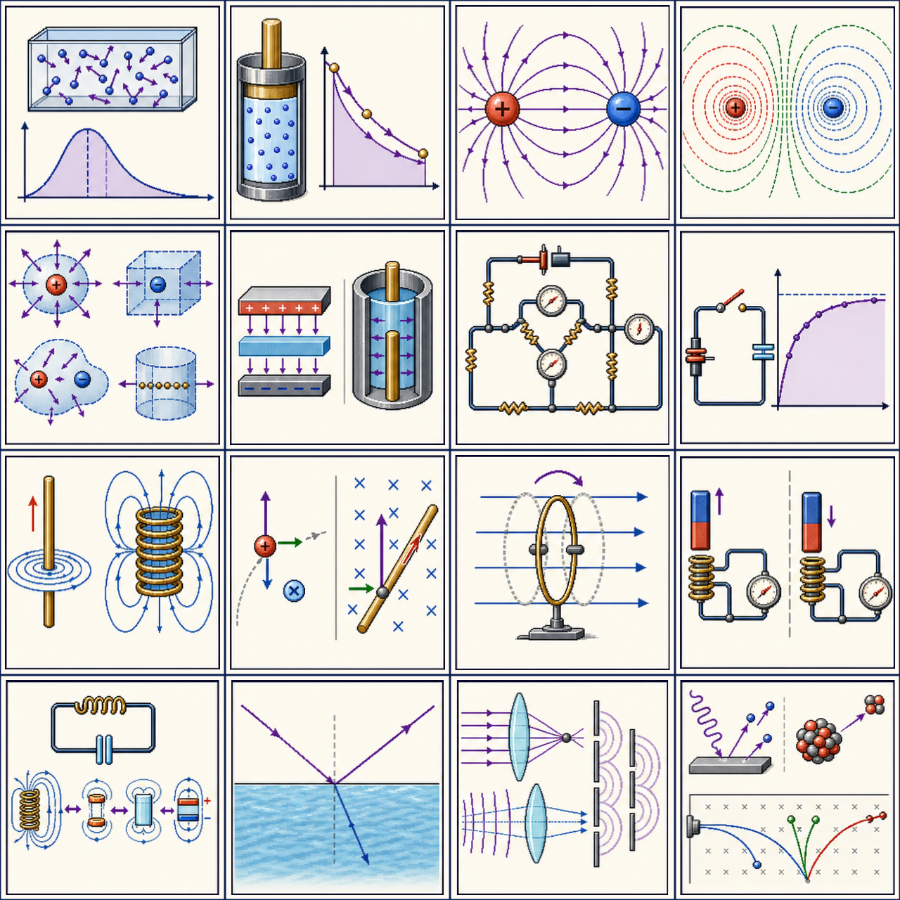
10. Reflection Does Not Begin at \(\theta_c\)
Below the critical angle, some light is generally reflected and some is transmitted. Total internal reflection means the transmitted propagating power drops to zero in an ideal lossless boundary, not that reflection was absent at smaller angles.
11. TIR Is Not Ordinary Metallic Reflection
A metal mirror reflects because electromagnetic fields drive charges in the conductor. TIR occurs at a transparent high-index-to-low-index boundary because Snell's law permits no propagating transmitted ray above \(\theta_c\).
12. Optical Fibers Guide Light
An optical fiber uses a core of index \(n_{\mathrm{core}}\) surrounded by cladding with slightly smaller index \(n_{\mathrm{clad}}\). Rays that strike the core–cladding boundary above its critical angle remain confined by repeated TIR:
Cladding provides a controlled boundary even when fibers touch, protects the core surface, and limits coupling between neighboring fibers. Excessive bending can reduce the internal incidence angle below critical, allowing light to escape.
Check a Guided Ray
A fiber has \(n_{\mathrm{core}}=1.50\) and \(n_{\mathrm{clad}}=1.46\). A ray inside the core reaches the boundary at \(78.0^\circ\) from the normal.
Because \(78.0^\circ>76.7^\circ\), the ray undergoes TIR at this encounter. A ray incident at \(74^\circ\) would not satisfy the condition and would partly transmit into the cladding.
13. Dispersion and Color
In many transparent materials, refractive index depends on wavelength: \(n=n(\lambda)\). Different colors therefore travel at different phase speeds and refract by different angles. A prism separates colors because its nonparallel faces prevent the second refraction from simply restoring the original direction.
When a problem supplies one index without mentioning wavelength, treat it as the effective index for the light being studied. Do not assume every color follows exactly the same path when dispersion matters.
14. Data Collection and Uncertainty
Use a semicircular block to reduce unintended refraction at one surface: aim the ray through the curved surface along a radius so it reaches that surface normally. At the flat face, measure incidence and refraction angles from the normal.
Collect several pairs, graph \(\sin\theta_2\) versus \(\sin\theta_1\), and use the slope to determine an index ratio. Include uncertainty from beam width, protractor resolution, surface alignment, and identifying the center of the ray. Near the critical angle, small angle errors can change whether a faint transmitted beam is observed.
15. Reliable Refraction Workflow
- Label the incident and transmitted media and their indices.
- Draw the normal at the exact point of incidence.
- Convert any surface-referenced angles to normal angles.
- Predict toward or away from the normal.
- Apply Snell's law and check that the sine result is physical.
- For possible TIR, verify direction before finding \(\theta_c\).
- Compare the answer with limiting cases and ray reversibility.
16. Common Traps
- Measuring angles from the surface.
- Saying frequency decreases in a slower material.
- Using mass density in place of refractive index.
- Assuming a normally incident ray must bend.
- Swapping \(n_1\) and \(n_2\) without swapping the angles.
- Using the critical-angle formula from low index to high index.
- Calling \(\theta_1=\theta_c\) a ray reflected with no boundary field.
- Assuming TIR occurs merely because the incidence angle is large.
- Forgetting that reflected light can exist below \(\theta_c\).
1. Light enters a higher-index material. Which of frequency, speed, and wavelength change?
Show reasoning and answer
Frequency stays fixed at a stationary boundary. Speed decreases because \(v=c/n\), and wavelength decreases because \(\lambda=v/f\).
2. A ray travels from \(n=1.20\) into \(n=1.60\). Does it bend toward or away from the normal?
Show reasoning and answer
Toward the normal: the second index is larger, so Snell's law requires \(\theta_2<\theta_1\).
3. Why does a normally incident ray not change direction at an index boundary?
Show reasoning and answer
With \(\theta_1=0\), Snell's law gives \(\sin\theta_2=0\), hence \(\theta_2=0\). Its speed and wavelength can still change.
4. Can light traveling from air into glass undergo total internal reflection at their boundary?
Show reasoning and answer
No. TIR requires travel from higher index to lower index; air-to-glass has \(n_1
5. For a glass-to-air boundary, \(\theta_c=42^\circ\). Classify incidence at \(35^\circ\), \(42^\circ\), and \(50^\circ\).
Show reasoning and answer
At \(35^\circ\), reflection and refraction occur. At \(42^\circ\), the limiting refracted ray runs along the boundary. At \(50^\circ\), TIR occurs.
6. A graph of \(\sin\theta_2\) versus \(\sin\theta_1\) has slope \(0.75\), and \(n_1=1.00\). Find \(n_2\).
Show reasoning and answer
The slope is \(n_1/n_2\), so \(n_2=n_1/0.75=1.33\).
Investigation: Map Refraction and Find a Critical Angle
Use the open educational PhET Bending Light simulation. Enable the protractor and intensity tools when available, and predict each ray before switching on the source.
- Hold the material pair fixed and record five \((\theta_1,\theta_2)\) pairs.
- Plot \(\sin\theta_2\) against \(\sin\theta_1\) and infer the index ratio from the slope.
- Reverse the material order and test ray-path reversibility.
- Send light from high index to low index, increase \(\theta_1\), and identify the critical-angle transition.
- Compare reflected intensity below and above the transition; explain why reflection is not created suddenly at \(\theta_c\).
For a real lab, use only a low-power classroom ray box or laser under instructor supervision. Keep beams below eye level and remove unintended reflective objects.
Official curriculum reference: College Board AP Physics 2 course page. The explanation and worked example are independently written for this study site.